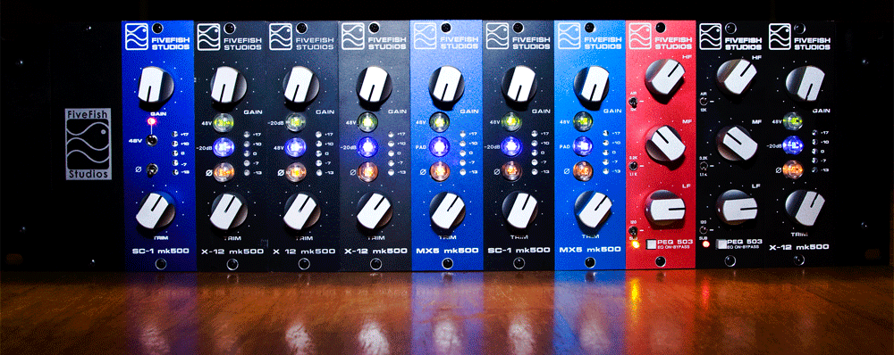
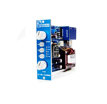
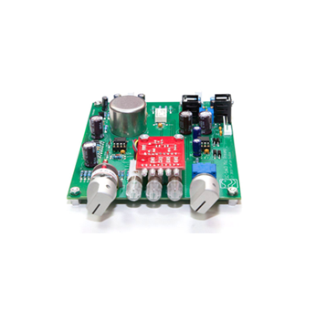
DIY Mic Pre Kits, Lunchbox Mic Preamp Kits, Power Supply Kits

DIY Forum
It is currently Tue May 21, 2013 4:25 am

All times are UTC - 5 hours


Post new topic Reply to topic  [ 5 posts ] 
Author Message
 Post subject: Just finished building the 1848 psu...
PostPosted: Fri Jul 13, 2007 8:01 pm 
Offline

Joined: Wed Jul 04, 2007 12:31 pm
Posts: 153
Location: California
..and thought I would share some thoughts on the build instructions while they are still clear in my head.

Documentation for the PSU makes some assumptions on the knowledge of the builder. For example the whole intro part of the SC-1 docs where it informs users about orientation of diodes is not in the PSU docs. This could be confusing for someone who has never built something like this. If you aren't familiar with the typical markings on the parts its hard to tell which way to insert them. The color pictures in the PDF show the orientation of the diodes but you have to look really close to see it (maybe its my monitor?), and they don't show up at all if you printed it in black and white like I did.

One that almost caught me up was the orientation for the LED's. + or - is not marked on the board and the docs say "long leg on the bottom". It isn't very clear which side is the bottom of the board. I went with the assumption that the top was the side with the regulators since most of the photos are oriented that way, but I'm still not sure.

The trim pots and the regulators are not clearly marked for orientation. I'm not sure whether it matters, but I made sure to match the picture for those.

Other than those minor things it was pretty good! Tonight I will power it up and see if anything explodes. ;) Then its on to my SC-1 boards! Its been quite a few years since I've done any electronics stuff and it was a lot of fun putting this together!


Top
 Profile  
 
 Post subject:
PostPosted: Fri Jul 13, 2007 9:32 pm 
Offline

Joined: Mon Jun 25, 2007 6:09 pm
Posts: 1261
Location: Music City
Thanks for the feedback scott! Very helpful.

Yes, I agree that some things that are "obvious" for a seasoned builder may not be clear for a first time builder, and I have not explained it in detail... also this PDF was rushed compared to the SC-1 documentation.

I'll update the PDF instructions with the issues/points you've raised and make it clearer, add more photos. Good suggestions, BTW!

I figure it will be easier saying the long leg of the LED or the short leg of the LED rather than saying positive or negative. The silkscreen marking shows one side as flat but it's not very clear.

Yes, the top of the PCB is the regulator side.

Quote:
>The trim pots and the regulators are not clearly marked for orientation. I'm not sure whether it matters, but I made sure to match the picture for those.


There is an outline on the board for the proper orientation of the trimmers. But even if it was inserted backwards, the circuit will still work. Though CW and CCW in the directions for adjusting the output voltages will have to be reversed.

_________________
Image


Top
 Profile  
 
 Post subject:
PostPosted: Fri Jul 13, 2007 11:48 pm 
Offline

Joined: Wed Jul 04, 2007 12:31 pm
Posts: 153
Location: California
I'm glad you found it helpful! I was mainly looking to point out anything that might seem ambiguous or non-obvious to someone who has never done anything like this before. I know when you are seasoned at something its very easy to overlook what you think is obvious and someone who is not can easily get completely lost (ask my boss when I try to explain stuff to him haha). I used to build heathkit stuff as a kid with my pop so it all started to come back to me as I built the kit and started checking connections but its been long enough that I had to stop and try to figure out some things. It's great! I'm having a ton of fun. :)

I didn't notice the one side as flat on the PCB for the LED but then my eyes aren't what they used to be. ;) Really the only things I could add would be maybe explain in a bit more detail in the parts where you list what to connect and when. Little things like which side the stripe on the diode should match against the PCB make all the difference. But still with a little patience and thought it wasn't hard to figure out!

In case I hadn't said it, you do awesome work Ruel and I'm happy to help support your project!


Top
 Profile  
 
 Post subject: And the verdict is...
PostPosted: Sat Jul 14, 2007 5:46 pm 
Offline

Joined: Wed Jul 04, 2007 12:31 pm
Posts: 153
Location: California
Success! It works perfectly. Voltages were way low (32V, 12V, and -11V) so I adjusted them up and all is well. Nice solid output too. Only fluctuations were +/-.01V! Granted thats without any load but still. :)

Now on to the pre-amps!


Top
 Profile  
 
 Post subject:
PostPosted: Sat Jul 14, 2007 6:16 pm 
Offline

Joined: Mon Jun 25, 2007 6:09 pm
Posts: 1261
Location: Music City
Woo hoo!!!!!

>Voltages were way low (32V, 12V, and -11V) so I adjusted them up and all is well.

That's normal at power up. The trimmers come from the factory adjusted at roughly their mid-point position.

_________________
Image


Top
 Profile  
 
Display posts from previous:  Sort by  
Post new topic Reply to topic  [ 5 posts ] 

All times are UTC - 5 hours


Who is online

Users browsing this forum: No registered users and 2 guests


You cannot post new topics in this forum
You cannot reply to topics in this forum
You cannot edit your posts in this forum
You cannot delete your posts in this forum
You cannot post attachments in this forum

Search for:
Jump to:  
Powered by phpBB © 2000, 2002, 2005, 2007 phpBB Group